
Better Card Cooling Basics – New Paste and Pads
WARNING: Breaking down your new video card will void your warranty and may result in loss of some or all functionality. Proceed at your own risk.
I’m writing this article as a result of making a warranty claim on a budget Radeon card.
The story:
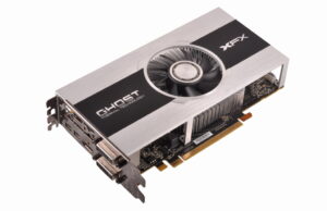
I bought an XFX Radeon R7 265 over two years ago. The card performed decently, but was hardly the top of the food chain, even for R7s. It had a single fan / shroud cooling system but maintained decent temps – around 65C under heavy load for long periods. The card recently and unexpectedly (and somewhat suspiciously) started to produce a black screen after POST. This happened immediately after a Windows 10 update, in fact on the restart after the update. Without a driver installed, or with the Windows VGA driver installed, it would produce an image without artifacts or other glitches common to dying cards. But with any Radeon driver, nothing but a black screen. I even updated the card BIOS thinking maybe the update had cut vital support for an element of DirectX. No dice. I RMA’d the card even though I wasn’t sure XFX would honor the warranty (BIOS update is a no-no).
But XFX is a solid company with customer-friendly support, so they not only replaced the card but gave me a newer, factory-overclocked version with a beefy (looking) dual fan cooling solution. Four heat pipes, large heat sink – it looks the part of an aggressive card, even though it’s a budget part.
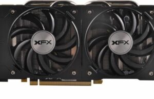
The problem? The new card gets hotter than the original ever did, and it shows in benchmarking. Repeated tests result in diminishing frame rates, a sure sign the cooler is not keeping up with heat dissipation demands, forcing the card to throttle itself down to keep from overheating. This is instructional in two ways. First, it demonstrates that even a moderate overclock results in substantially more heat generation. The original card had the standard R7 265 base clock of 900MHz. One year’s improvement had raised the R7 370 base clock to 975MHz. The new card runs at 1050MHz base and will hit 75C within about 90 seconds of starting a benchmark. Leave it running and it heads toward 80C. So 150MHz over the architecture’s original limit is generating over 20% more heat, despite the fact that the new card does have a better cooling solution.
While this temperature is within the card’s tolerances, heat is the implacable enemy of computers and I’m not happy with the cooling. In addition, the new card is extremely loud under load, and I’m not one who’s normally bothered by loud fans. But when this little guy spools up it really bothers me. This situation is an ideal opportunity to demonstrate the correct way to break down a card and hopefully see a cooling improvement, and it’s always possible the factory thermal compound, which for cards is a semi-solid square that somewhat resembles a small sheet of clay, was misplaced on the card during assembly and that defect is what’s causing these temps.
The nature of the problem, I think is that the over-sized heat sink while impressive to behold does not make contact with the VRM portion of the card. Instead, it relies on the warm air being blown through the heat sink in order to cool this crucial structure. Engineers will be the death of us yet. At any rate, I’m a little dubious about being able to improve the cooling substantially as normally, I upgrade not only the thermal paste but also chuck the cheap pads (which bridge the gap between VRM components and a “proper” heat sink in favor of higher-quality pads with superior heat conductivity. In this case I don’t think that will do any good (and could actually exacerbate the problem) and I don’t have any pad material thick enough to make contact with the heat sink in any event.
One last warning. Again, attempting this will void the warranty on a new card and although it’s not a difficult task, even experienced techs have tried and destroyed their hardware as a result. If you’re new to PC gaming, it’s best to reserve this as a tactic to prolong the life of your card, as the thermal interfaces do dry out (paste) or break down (pads) over time.
For instance, a few years ago I owned another card that ran well for several years. However, it started to artifact and suffer intermittent, momentary black screen issues at about 3 1/2 years into its service life. Since it was already out of warranty, and not functioning normally I was risking little by breaking it down and replacing the thermal interfaces. By doing so, I postponed the inevitable and though I no longer use it in any of my systems, I could in a pinch if I had to; it now serves as a diagnostic tool when necessary. It’s important to note that although the card now functions more normally, one can never eliminate the symptoms once they have begun. CPUs and GPUs are delicate in a sense. Once they overheat they can never be returned to 100% functionality.
The photos below demonstrate the right way to tear down and refurbish the serviceable portion of the cooling solution on a particular card, XFX R7-370B-CDFR. It is not intended to be an all-encompassing guide, but rather to demonstrate the steps needed to perform the same task on any air or passively cooled device.
What you will need:
Philips 0 or 00 screwdriver
X-acto knife, scalpel or other very sharp tool
Good quality thermal compound – I like Arctic MX-4 but there are a number of suitable products on the market
Good quality thermal pads – Fujipoly is pretty much the industry standard for this application (though , get material that is at least 1mm thick, the .5mm pad material is not thick enough to maintain adequate contact with the heat sink! Fujipoly pads have a thermal conductivity of 11.0 W/mK (Watts per meter-Kelvin, if you care), more than double the heat transfer capacity of the OEM pads. If you’re on a tight budget, you can use cheaper pads that are common on eBay, but don’t buy any that you can’t confirm have a thermal conductivity of at least 5.0 W/mK, which is the minimum spec for all the cards I’ve ever worked on.
Anti-static surface
Patience – its’ not about doing it fast, but doing it right!
The Procedure
Further reading:
https://multimedia.3m.com/mws/media/122268O/characteristics-of-thermal-interface-materials.pdf


Copyright © 2019 GPUnerd.
gpunerd.com is a participant in the Amazon Services LLC Associates Program, an affiliate advertising program designed to provide a means for sites to earn advertising fees by advertising and linking to amazon.com. Beware: it is possible that the information provided above is not currently up-to-date or guaranteed to be accurate. Pay close attention to the product description by retail shops, GPUnerd.com is not liable for incorrectly displayed products and/or prices.